Monday, November 27, 2017

ARCH 653_Final Project_Accessing BIM Data for Creative Design and Applications

In final project I worked on the same model as my Project 1 - Two In One House.

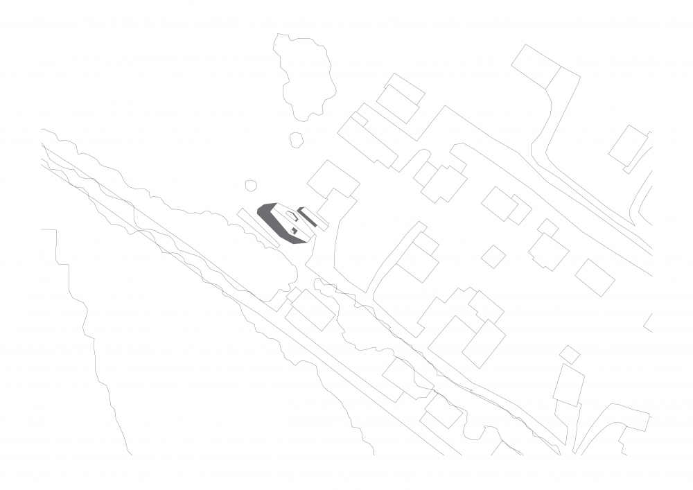
(For details of the project please refer to previous post.)

DEFINING MASS, WALLS AND PARAMETERS

I started with a simplified version of mass model, uploaded to Revit Project. Then I associated mass with Dynamo and created the walls by using Wall.ByFace Built-in node (to obtain this node I needed an update in Dynamo).


For generating the roof, I used same node, but this time I selected the roof planes from mass.


In the next step, I chose mass family by Family Types node, and by using Get Family Parameter, I defined the parameters one by one.
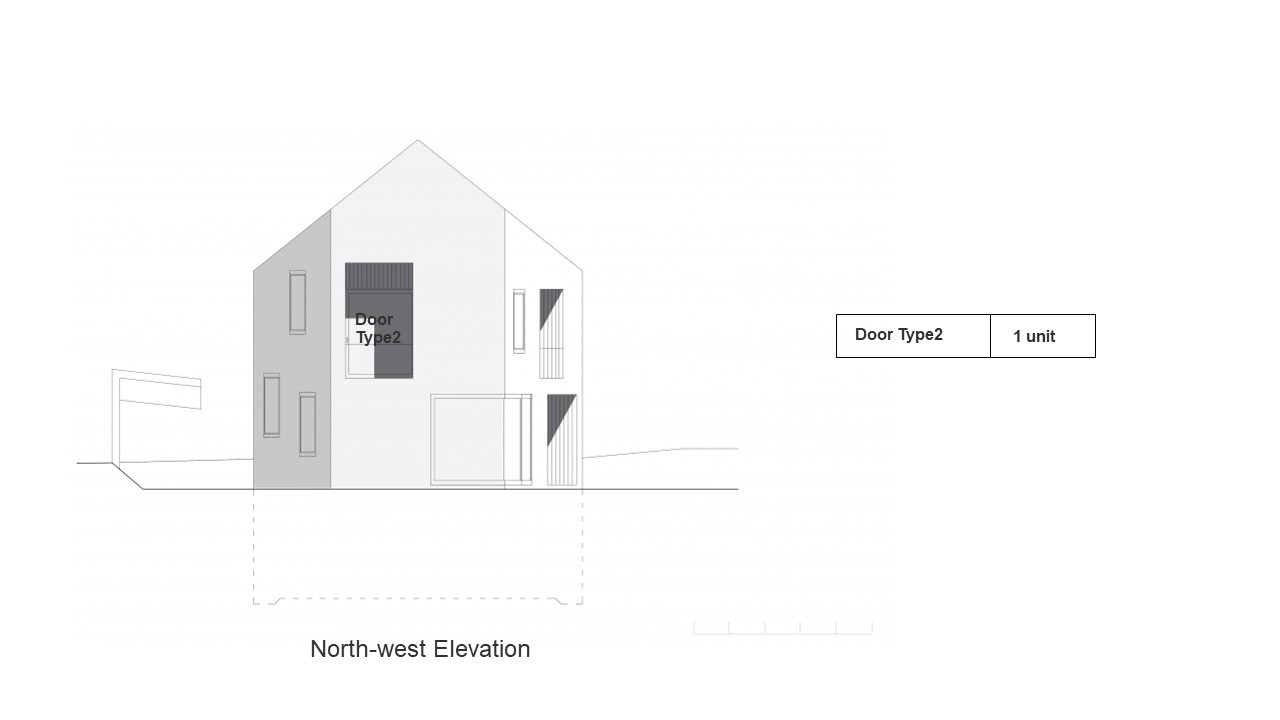

DEFINING FACADE

I used several methods and combination of nodes for this process; however none of them gave the solution. My approaches are below:

1. Approach:
By using categories and AllElementsof Category, I selected walls. The output of this node is expected to be Walls, but in this case it was Facewalls.
I used Place.Elements.InWalls from the same named package, and Place.Window.Doors.InWalls from the same named package. Both nodes gave null list.


2. Approach:
First, I selected the face on which the window will be hosted. I found the vertices and by picking and translating one of the corner points I generated the corner points of the window. I used HostedInstance.ByPoints node by Springs package. but this node gave empty list.


3. Approach:
I used HostedInstance.ByPoints node by Springs in another combination. First, I selected categories of walls. When Categories node was plugged into All Elements of Category, it again gave Facewalls. Also, both Element.GetLocation node and Element.Location+ by Clockwork package node gave null list.


Before this method I have tried other methods and several nodes.


--------------------------------------------------------------------------------------------------------------------------

OTHER METHODS I TRIED

METHOD 1 (FROM SCRATCH  IN DYNAMO BY GENERATING & TRANSLATING POINTS)

I started to model my mass in Dynamo from scratch by using points. I created the origin (0,0,0) point and by translating it and adding points I created all the corner points of the mass.

1. GENERATE POINTS


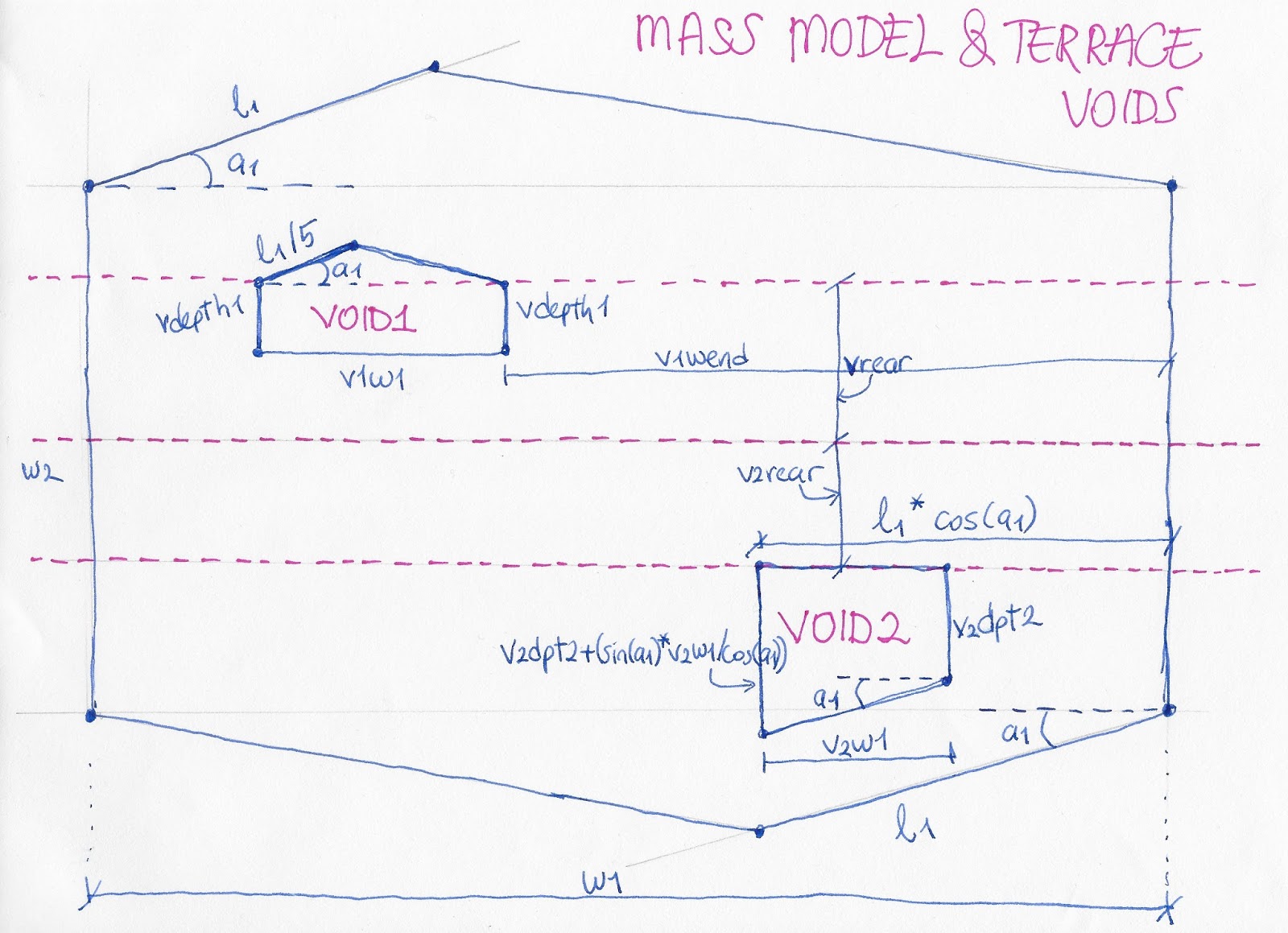
2. DEFINE PARAMETERS

By using number sliders and vectors, I defined the parameters as translation in X and Y axes.


For the height parameters, the points were translated in Z axis and again number slider were used. Mid height was defined as units, lowest height and peak height were defined as dependent to the mid height with changeable ratios.


3. GENERATE SURFACES

After generating all the corner points, I created polygons and surfaces, both for the walls and the roof.


4. CREATE FLOORS

I also created a polygon for the footprint of the mass and by defining levels, I translated it in Z axis. By using Floor.ByOutlineTypeAndLevel node, I generated the floors.


After generating the mass in Dynamo with its parameters, second step is to generate parametric walls, floors and roof.

The problems started when I tried to generate the walls from the surfaces I created.

Creating Parametric Walls

FAILURES & SOLUTIONS


Failures

I used several nodes and combination of them in order to create parametric walls.

1. I used Wall.ByFace node by Clockwork Package, it gave empty list.

Later I learned that I need to upgrade my Dynamo to use OOTB Wall.ByFace node which means Dynamo itself has an inbuilt Wall.ByFace node in the latest version. (My version was the one that comes in with Revit 2018)

However,  OOTB Wall.ByFace node gave empty list, too.

2. I used RevitFace.FromDynamoSurface, and got again empty list.

I learned that this node does not convert a surface generated in Dynamo to Revit. First, bring geometry to Revit & bring its faces back to Dynamo.

3. So I used ImportInstance.ByGeometry > SelectFace > RevitFace.FromDynamoSurface in order to bring my geometry to Revit and retrieve to Dynamo.

However, it gave empty list, too.

4. I used ImportInstance.ByGeometry > TopologyFaces > RevitFace.FromDynamoSurface

This process gave the surfaces, but  OOTB Wall.ByFace node did not work even if I tried the longest lacing and gave warning.

Warning: One or more of the input types are not matching. Couldn't find a version of ByFace that takes arguments of type (__array,__array,__array)


Then, I learned that, for OOTB Wall.ByFace node to work, the faces need to be the faces of a mass surface in Revit.

5. I have imported my mass to Revit by  ImportInstance.ByGeometry. I retrieved the faces of Revit mass by using SelectFace node. But OOTB Wall.ByFace node got again empty list. (The longest lacing did not work.)


Solution

I used Wall.ByCurveAndHeight node by benefiting from the ImportInstance.ByGeometry faces. Wall.ByCurveAndHeight node has height input which results in the height parameter of points being invalid.

See below:


This node gave the vertical walls which works parametricly and a warning: "Warning: Wall.ByCurveAndHeight operation failed.
The curve argument is not valid for rectangular wall creation.
Parameter name: curve"


Limitation

Wall.ByCurveAndHeight node has height input and it results all the walls having same height.


Creating Parametric Floors

I used a combination of the same process and nodes (Wall.ByCurveAndHeight, ImportInstance.ByGeometry) as in the wall generation and create floor step above to create parametric floors.
See below:


Deleting Unwanted Model Elements

After each parametric change, Revit keeps the older version too, and this makes a confusion since both the oldest and latest versions overlap.

I used Elements.Delete node by Archi-lab.net Package to delete older model elements. But I needed to select them manually by using Tab, which was not very practical. After running Dynamo, since the model elements were deleted, Select Model Elements nodes became empty. Manual selection is required to delete the model elements after each parametric change.


METHOD 2 (USING MASS MODEL)

I used Family Types node to select mass family, and then defined the parameters.

By using one of the element outputs, I got surfaces and defined walls by using Wall.ByCurveAndHeight.


Creating Parametric Roof


After creating the walls, I needed to pick the top corner points in order to define a base for roof. First, I selected the top surfaces of each wall and found the vertices. From the list of vertices, I picked up the corner walls. I found the exact points by experimenting. 


For creating roof, base points and peak points were needed. Below is the generating the peak points by benefiting from corner points.


  By using Roof.SlabShapeByPoints node, I generated the whole roof, but the result was not satisfying. So I tried to generate the roof in two pieces.


However, the result is again not satisfying.


References:

https://forum.dynamobim.com/t/dynamo-mass-and-revit-wall-by-face/4543/8
https://forum.dynamobim.com/t/revitface-fromdynamosurface-empty-list-problem/16718/9
http://dynamobim.org/forums/topic/point-extraction-from-surface-and-placing-components-at-those-points/
http://dynamobim.org/forums/topic/placing-windows/#post-38349
http://dynamobim.com/forums/topic/how-to-put-a-door-or-window-object-on-the-wall-2/
https://www.youtube.com/watch?v=1fzJbxJMzQk


Sunday, October 22, 2017

ARCH 653_Project 1_Parametric BIM

TASK:  to create a Building Information Model and a Parametric Design for a selected case study

CASE STUDY: Two in One House, Switzerland


PROJECT INFORMATION


       Architects

Clavienrossier Architectes

Location
Geneva, Switzerland

Function
Residence

Project Year
2012

Photographs
Roger Frei


The site is located on the edge of a residential zone on the outskirts of Geneva, flanked on its southern border by a forest and opening out to fields to the west. It sits right on the line between the city and nature.

The building, backed by a paved access ramp, is placed in the northeast corner of the site. The space between the building and the forest allows for a swimming pool and a large open garden.
The program includes two apartments of differing size, a continuous party wall separates the two.

A pitched roof over a diamond shaped plan, allows each apartment to have its own orientation. This distinct geometry allows for a greater degree of privacy for the residents and when viewed from the outside, gives the impression of a single unit.
The split geometry of the facades makes it difficult to get a grasp of the actual size of the building, giving each individual facade a more domestic scale.
The exterior envelope of the building is entirely composed of integrally-colored concrete, including the roof. Loggias built out of larch, perforate the facade and the roof of the building. The building conforms to very high energy standards.


Site Plan
1. Floor Plan
2. Floor Plan
Attic Plan
South-west elevation
North-east Elevation
North-west Elevation
South-east Elevation
Detail

PARAMETRIC CONCEPTUAL MASS


Final mass modeling is seen above. It is made in three stages:
1. Parametric Conceptual Mass
2. Parametric Voids
3. Parametric Terrace Voids


1. PARAMETRIC CONCEPTUAL MASS

I started with parametric lines on Level 1.


Here are the steps:

1. Open New>Conceptual Mass>Mass

2. Go to Level 1

3. Put 2 reference points on the horizontal reference plane with dimension and give parameter


4.  On level 1 reference plan, draw reference line #1 from the left point, with rotation parameter (3D snapping off)

5. Draw another reference line (#2) on top of #1, with length parameter (3D snapping on)


6. Draw reference line (#3) using Draw on face + 3D snap from end of line #2 and the right point

7. Select the plane of left point by using tab key, draw vertical reference line (#4) with length parameter from the left point (3D snapping off)

8. Select the plane of right point by using tab key, draw vertical reference line (#5) with length parameter from the right point (3D snapping off)


9. Select the plane of Line #5, draw reference line (#6) from end of (#5), with rotation parameter (3D snapping off)

10. Draw another reference line (#7) on top of #6, with length parameter (3D snapping on)

11. Draw the final reference line (#8) from end of (#7) to the end of (#4) (3D snapping on)


12. Create form using the reference lines (do not select line (#1) and line (#6))

13. Extrude the parametric lines with a height parameter


2. PARAMETRIC VOIDS


For the roof form, I made two parametric void bases (symmetrical triangles) on the East Elevation and extrude them. I used a trigonometric formula to define triangle length. 

Here are the steps:

1. Create a reference line parallel to the central plane. Between the central plane and the parallel reference line(#1) put dimension with a length parameter defined by trigonometric formula

2. Put a reference point(#2)>align to top level, lock > align to central plane, lock

3. Reference line #3 (3D snap off)>align to top level, lock (on reference point plane)

4. Reference line #4 on top of Reference line #3 (3D snap on)> align end of the line to parallel Reference line, lock (on reference point plane)

5. Select parallel line plane> Reference line #5 start from top level on the Reference line #1 (3D snap off)>align its end to level #3, lock

6. Reference line #6 (3D snap on) from end of #5 Reference line to initial reference point


3. PARAMETRIC TERRACE VOIDS

For the terrace voids, I drew parametric lines very similar to conceptual mass lines but this time on Level 3. Lengths, angles and locations are defined  in relation with the conceptual mass by benefiting simple formulas and trigonometric functions.

As a start I created parametric lines just the same way as I did the conceptual mass parametric lines.


PARAMETRIC CHANGES


change in angle parameter values


change in height parameter values

change in length parameter values

change in width parameter values
change of size and location in terrace void parameter values


PARAMETRIC FACADE

List of Windows and Doors


Number of windows and Doors


Window Type1 North-east elevation a 2
b 3
South-west elevation a 1
South-east elevation 1
Window Type2 North-east elevation a 1
South-west elevation b 2
Door Type1 North-east elevation a 2
Door Type2 North-west elevation 1
Door Type3 South-west elevation a 1
Door Type4 South-west elevation b 1
Door Type5 South-west elevation a 1
Door Type6 South-west elevation b 1
Door Type7 South-east elevation 1
Window + Door Type1 North-east elevation 1
Window + Door Type2 South-west elevation a 1
Window + Door Type3 South-west elevation b 1


As seen above, there are several custom made windows and doors. 

I simplified them:

Window Type 1 and Window Type 2 > Same Family, Different Types


Parameters: Width, height, material

Door Type 1


Parameters: Width, height, angle, material


Door Type 2 and Door Type 7 > Same Family, Different Types


Parameters: Width, height, material, angle, thickness and height of the frame, thickness of side panels


Door Type 3 and Door Type 4 > are considered as the same


Parameters: Width, height, angle, material


Door Type 5 and Door Type 6 > are considered as the same


Parameters: Width, height, angle, material


Window+Door Type 1 and Window+Door Type 3 > Same Family, Different Types


Parameters: Width, height, material, panels' width, panels' height


Window+Door Type 2


Parameters: Width, height, material, angle, thickness and height of the frame


RENDERING


References
  1. http://www.archdaily.com/373375/two-in-one-house-clavienrossier-architectes (text) 
  2. http://www.clavienrossier.ch/projets/tous#78 (images)
  3. https://www.youtube.com/watch?v=II11YOFC184 (modeling, design intent)
  4. https://www.youtube.com/watchv=U6Hc26vqTO4&t=696s&index=9&list=PLov22Ah1hX_xJv1pOGWYeGo2HzVzFr0CW
  5. https://www.youtube.com/watchv=V7prI2iBvrc&index=10&list=PLov22Ah1hX_xJv1pOGWYeGo2HzVzFr0CW
  6. https://www.youtube.com/watchv=zknX9wutWM&list=PLov22Ah1hX_xJv1pOGWYeGo2HzVzFr0CW&index=11
  7. https://www.youtube.com/watchv=l63x_NnKnl0&list=PLov22Ah1hX_xJv1pOGWYeGo2HzVzFr0CW&index=1