
Definition:
Algorithms and Scripting for Parametric Design
Creating more powerful model definition and better defined parametric designs, with the use of the two advanced methods:
(1) algorithms, especially Genetic Algorithm; and/or
(2) scripting that can expend the capability of existing tools and help you create your own algorithms.
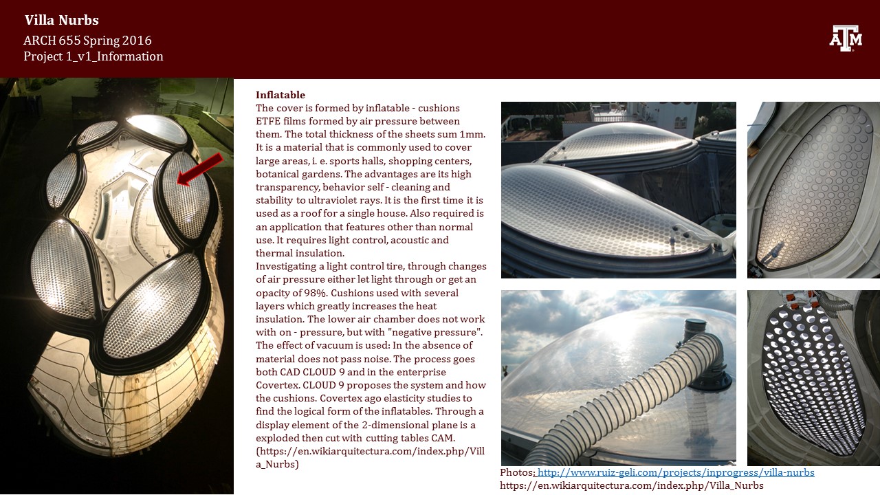
Case Study: Villa Nurbs, Spain by Architect Enric Ruiz-Geli (Cloud 9)
Goals:
In my final project, my goal is to design a new facade to Villa Nurbs with respect to the radiation values.
Parametric Modeling:
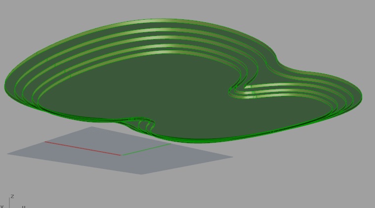
In this final project, I recreated only the body of my previous parametric modeling. In Project1 presentation, I was advised to start with points by Prof. Dr. Wei Yan.
So firstly, I drew the curves of six different etfe pillows in Rhino by using their layout. I put points in their control points and defined the points in Grasshopper. I recreated the nurbs curves in Grasshopper with the help of these points.


For the roof of the building, I got used the curves by offsetting them; and I baked the curves. In Rhino, I joined them and created the threshold. With the "Boundary" node, the roof was generated.

Since the form of the body is not symmetrical, I created two different sections via points.

This time, I used "Sweep 2" node for the skin instead of "Loft" node.

"Boundary" node was used to generate the floor slab.
Ladybug Analysis:

Location: Gerona, Spain
Coordinates: 42° 14' 49" N, 3° 7' 28" E
In order to achieve my goal, I needed the radiation values. I decided to use Ladybug plugin for "Radiation Analysis". Villa Nurbs is in Gerona, Spain. I visited energyplus website and downloaded the epw file (link is seen below).
In addition, I assumed the Y_axis is pointing the North direction; so I rotated my model to be located as seen on Google map.

I started with "Ladybug" node. After seeing the "Flying" message, I used "Open Epw Weather File" node. By connecting a "Boolean Toggle" and setting it "True" makes you browse your epw file. It is important to save your epw file to a place to find easily.

Next step was to connect the epw file to the "GenCumulativeSkyMtx" node. This node also required "Boolean Toggle". CumulativeSkyMtx output was connected to "SelectSkyMtx" node and this node was connected to the "Radiation Analysis" node as seen above. Some inputs of "Radiation Analysis" were flattened as default. I used Unit Y vector for North direction. "Grid size" input could be changed parametrically. In this model, the value was"8". By setting the Boolean Toggle "True", radiation values matched with colors as in the legend and results of the analysis could be seen on the model in Rhino.

The radiation analysis seen above is correct but when I first tried it, it was incorrect. In Ladybug, I generated sun path with "Sun Path" node. When I first generated radiation analysis, the facade was all blue in the south direction which should normally gained more sun light than north facade. Therefore, "Flip" node was used to correct the normal of the skin surface. After using "Flip" node (seen in the third image from the start), radiation analysis became as above.

In the sun path diagram, conditional selection was applied (comfort zone is ignored): The location of sun was shown when the dry bulb temperature was more than 22C and global horizontal radiation was more than 630Wh/m2.

Radiation values were required to be used as the input for the design of a new facade. My aim is to design sun shade with respect to these values. Before using the values, they had to be converted. Python node was used for this conversion.


The numbers which were connected to x input of Python node were all decimal numbers. Since the values were in a list, x should be converted to "List Access" and for the numbers, "float" has to be chosen. This menu was accessed by right clicking the "x" input.
Weaverbird's Stellate/Cumulate node was used to generate sun shade. Converted values became the height of each pyramid. If the piece got less sunlight the height of pyramid was more. The pyramids on blue parts were sharp pointed as seen on the baked one on the left.

The bottom area of pyramids could be changed parametrically with the number slider which was used as "_gridSize_" input in the "radiationAnalysis" node. After forming pyramids, I would like to obtain the result of "Weaverbird's Picture Frame" node. This time, less sunlight should match thinner frame which meant smaller value. Therefore, the list of values generated by Python node should be reversed. In addition, there was another tricky part which was the values of matching the faces. When the first Python node was used, the number of grid was equal to the bottom number of pyramids. After pyramids were generated, the number of faces was multiplied by 4 since the pyramids have 4 faces. Each value should also be multiplied by 4 in order to match the number of faces. "Weave" node was used for this multiplication. Each value repeated itself 4 times as seen in the list.


After framing, I tried another design with the same values. My aim was to create a panel wall. However the mesh of Ladybug analysis and the grid of the panels did not match. In addition, the panels did not reflect the expected results which had to be in accordance with the analysis values.
The second solution worked: By exploding the analysis mesh coming from Ladybug, the vertices of the panels were generated. For the mesh explosion node, I had downloaded Meshedit tools from this link http://www.food4rhino.com/project/meshedittools
With this method, I did not require to use the paneling tools and I obtained the correct result which is seen below.


References:
http://www.grasshopper3d.com/forum/topics/question-about-weaverbird-picture-frame?xg_source=activity
https://en.wikiarquitectura.com/index.php/Villa_Nurbs
http://www.ibpsa.org/proceedings/bs2013/p_2499.pdf
https://enengyplus.net/
grasshopper3d.com/group/ladybug
https://www.youtube.com/playlist?list=PLruLh1AdY-Sj_XGz3kzHUoWmpWDXNep1O
https://www.youtube.com/watch?v=AZL2lJroaNE&index=2&list=PLruLh1AdY-Sj_XGz3kzHUoWmpWDXNep1O
https://www.youtube.com/watch?v=sRfd4K3b9ew&index=3&list=PLruLh1AdY-Sj_XGz3kzHUoWmpWDXNep1O
https://www.youtube.com/watch?v=Fwe9ZJnTSH0&index=4&list=PLruLh1AdY-Sj_XGz3kzHUoWmpWDXNep1O
http://www.grasshopper3d.com/group/panelingtools
http://designalyze.com/intro-scripting-python-rhino/


