TASK: to create a Building Information Model and a Parametric Design for a selected case study
CASE STUDY: Two in One House, Switzerland

Architects
Clavienrossier Architectes
Location
Geneva, Switzerland
Function
Residence
Project Year
2012
Photographs
Roger Frei
The site is located on the edge of a residential zone on the
outskirts of Geneva, flanked
on its southern border by a forest and opening out to fields to the west. It
sits right on the line between the city and nature.
The building, backed by a paved access ramp, is placed in the
northeast corner of the site. The space between the building and the forest
allows for a swimming pool and a large open garden.
The program includes two apartments of differing size, a
continuous party wall separates the two.
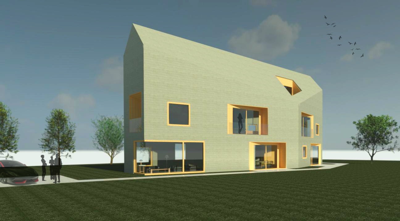
A pitched roof over a diamond shaped plan, allows each apartment
to have its own orientation. This distinct geometry allows for a greater degree
of privacy for the residents and when viewed from the outside, gives the
impression of a single unit.
The split
geometry of the facades makes it difficult to get a grasp of the actual size of
the building, giving each individual facade a more domestic scale.
The exterior envelope of the building is entirely composed of
integrally-colored concrete, including the roof. Loggias built out of larch,
perforate the facade and the roof of the building. The building conforms to very high energy
standards.


Site Plan

1. Floor Plan

2. Floor Plan

Attic Plan

South-west elevation

North-east Elevation

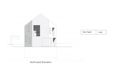
North-west Elevation

South-east Elevation

Detail
PARAMETRIC CONCEPTUAL MASS
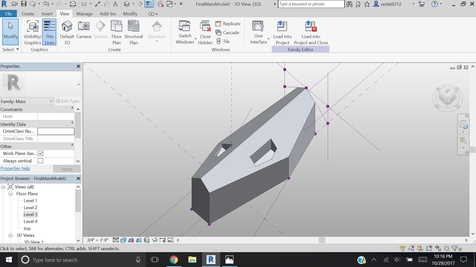
Final mass modeling is seen above. It is made in three stages:
1. Parametric Conceptual Mass
2. Parametric Voids
3. Parametric Terrace Voids
1. PARAMETRIC CONCEPTUAL MASS
I started with parametric lines on Level 1.

Here are the steps:
1. Open New>Conceptual Mass>Mass
2. Go to Level 1
3. Put 2 reference points on the horizontal reference plane with dimension and give parameter

4. On level 1 reference plan, draw reference line #1 from the left point, with rotation parameter (3D snapping off)
5. Draw another reference line (#2) on top of #1, with length parameter (3D snapping on)

6. Draw reference line (#3) using Draw on face + 3D snap from end of line #2 and the right point
7. Select the plane of left point by using tab key, draw vertical reference line (#4) with length parameter from the left point (3D snapping off)
8. Select the plane of right point by using tab key, draw vertical reference line (#5) with length parameter from the right point (3D snapping off)
7. Select the plane of left point by using tab key, draw vertical reference line (#4) with length parameter from the left point (3D snapping off)
8. Select the plane of right point by using tab key, draw vertical reference line (#5) with length parameter from the right point (3D snapping off)

9. Select the plane of Line #5, draw reference line (#6) from end of (#5), with rotation parameter (3D snapping off)
10. Draw another reference line (#7) on top of #6, with length parameter (3D snapping on)
11. Draw the final reference line (#8) from end of (#7) to the end of (#4) (3D snapping on)
10. Draw another reference line (#7) on top of #6, with length parameter (3D snapping on)
11. Draw the final reference line (#8) from end of (#7) to the end of (#4) (3D snapping on)

13. Extrude the parametric lines with a height parameter


2. PARAMETRIC VOIDS

For the roof form, I made two parametric void bases (symmetrical triangles) on the East Elevation and extrude them. I used a trigonometric formula to define triangle length.
Here are the steps:
1. Create a reference line parallel to the central plane. Between the central plane and the parallel reference line(#1) put dimension with a length parameter defined by trigonometric formula
2. Put a reference point(#2)>align to top level, lock > align to central plane, lock
3. Reference line #3 (3D snap off)>align to top level, lock (on reference point plane)
4. Reference line #4 on top of Reference line #3 (3D snap on)> align end of the line to parallel Reference line, lock (on reference point plane)
5. Select parallel line plane> Reference line #5 start from top level on the Reference line #1 (3D snap off)>align its end to level #3, lock
6. Reference line #6 (3D snap on) from end of #5 Reference line to initial reference point

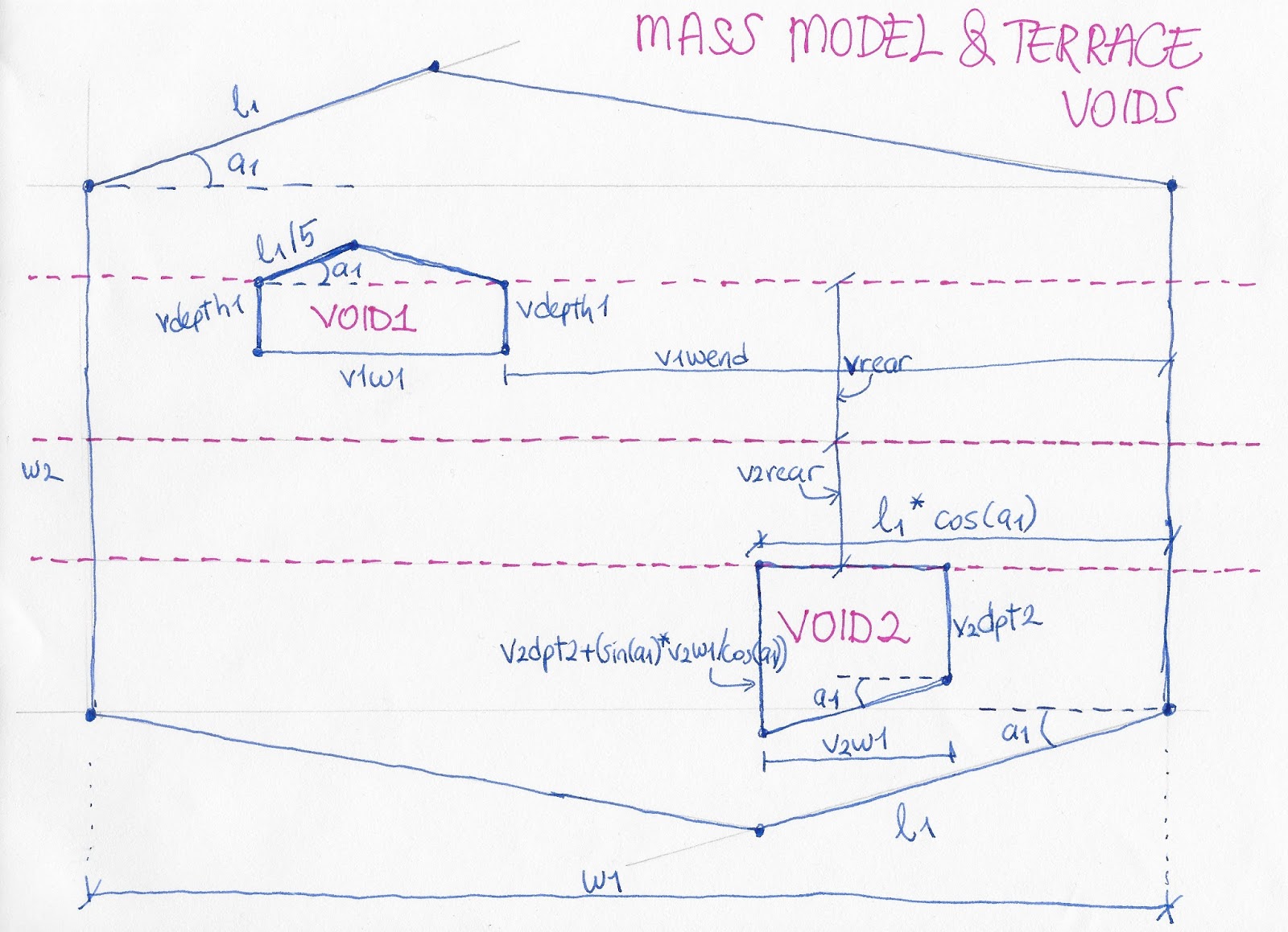
3. PARAMETRIC TERRACE VOIDS
For the terrace voids, I drew parametric lines very similar to conceptual mass lines but this time on Level 3. Lengths, angles and locations are defined in relation with the conceptual mass by benefiting simple formulas and trigonometric functions.
As a start I created parametric lines just the same way as I did the conceptual mass parametric lines.

PARAMETRIC CHANGES


PARAMETRIC FACADE


Number of windows and Doors


Parameters: Width, height, angle, material
Door Type 5 and Door Type 6 > are considered as the same

Parameters: Width, height, angle, material
Window+Door Type 1 and Window+Door Type 3 > Same Family, Different Types

Parameters: Width, height, material, panels' width, panels' height
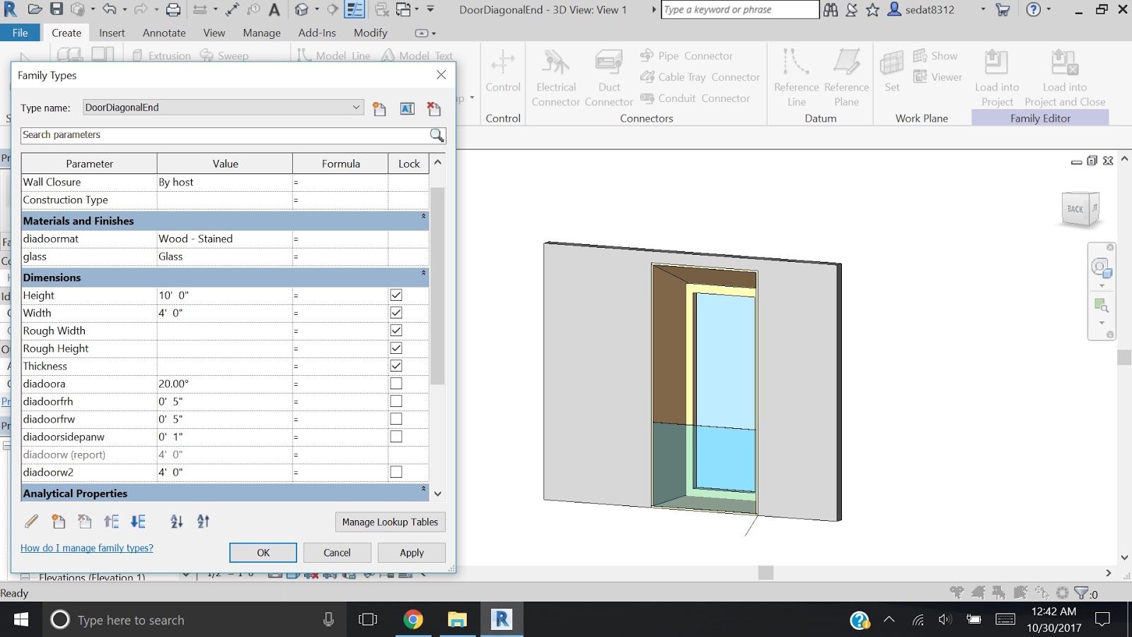
Window+Door Type 2

Parameters: Width, height, material, angle, thickness and height of the frame
RENDERING


References
For the terrace voids, I drew parametric lines very similar to conceptual mass lines but this time on Level 3. Lengths, angles and locations are defined in relation with the conceptual mass by benefiting simple formulas and trigonometric functions.
As a start I created parametric lines just the same way as I did the conceptual mass parametric lines.
PARAMETRIC CHANGES

change in angle parameter values

change in height parameter values

change in length parameter values

change in width parameter values
change of size and location in terrace void parameter values
PARAMETRIC FACADE
List of Windows and Doors


| Window Type1 | North-east elevation | a | 2 |
| b | 3 | ||
| South-west elevation | a | 1 | |
| South-east elevation | 1 | ||
| Window Type2 | North-east elevation | a | 1 |
| South-west elevation | b | 2 | |
| Door Type1 | North-east elevation | a | 2 |
| Door Type2 | North-west elevation | 1 | |
| Door Type3 | South-west elevation | a | 1 |
| Door Type4 | South-west elevation | b | 1 |
| Door Type5 | South-west elevation | a | 1 |
| Door Type6 | South-west elevation | b | 1 |
| Door Type7 | South-east elevation | 1 | |
| Window + Door Type1 | North-east elevation | 1 | |
| Window + Door Type2 | South-west elevation | a | 1 |
| Window + Door Type3 | South-west elevation | b | 1 |
As seen above, there are several custom made windows and doors.
I simplified them:
Window Type 1 and Window Type 2 > Same Family, Different Types

Parameters: Width, height, material
Door Type 1

Parameters: Width, height, angle, material
Door Type 2 and Door Type 7 > Same Family, Different Types
Parameters: Width, height, material, angle, thickness and height of the frame, thickness of side panels
Door Type 3 and Door Type 4 > are considered as the same

Door Type 5 and Door Type 6 > are considered as the same

Parameters: Width, height, angle, material
Window+Door Type 1 and Window+Door Type 3 > Same Family, Different Types

Parameters: Width, height, material, panels' width, panels' height
Window+Door Type 2

Parameters: Width, height, material, angle, thickness and height of the frame
RENDERING

References
- http://www.archdaily.com/373375/two-in-one-house-clavienrossier-architectes (text)
- http://www.clavienrossier.ch/projets/tous#78 (images)
- https://www.youtube.com/watch?v=II11YOFC184 (modeling, design intent)
- https://www.youtube.com/watchv=U6Hc26vqTO4&t=696s&index=9&list=PLov22Ah1hX_xJv1pOGWYeGo2HzVzFr0CW
- https://www.youtube.com/watchv=V7prI2iBvrc&index=10&list=PLov22Ah1hX_xJv1pOGWYeGo2HzVzFr0CW
- https://www.youtube.com/watchv=zknX9wutWM&list=PLov22Ah1hX_xJv1pOGWYeGo2HzVzFr0CW&index=11
- https://www.youtube.com/watchv=l63x_NnKnl0&list=PLov22Ah1hX_xJv1pOGWYeGo2HzVzFr0CW&index=1