Definition:
Project 1_Parametric Modeling and Physically-based From Finding
- Creating parametric form (mass and skin) for the curved design by using Rhino/Grasshopper
- Creating a parametric, physically-based model for a part of the design by using Kangaroo and Weaverbird.
- Analyzing selected curved surfaces in the project, in terms of geometry (dimensions, areas, curve tangents, curvatures, etc. using the Analyze/Analysis functions of Rhino and Grasshopper), and physics by using Kangaroo.
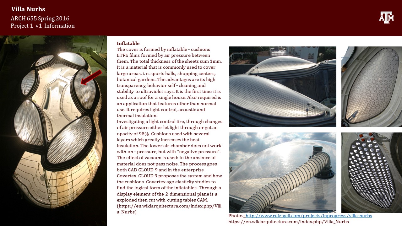
Case Study: Villa Nurbs, Spain by Architect Enric Ruiz-Geli (Cloud 9)
Introduction:


Parametric Modeling:
In this case study, I create my parametric modeling in five parts:
- Columns (Feet)
- Transition Contours (Between columns & Body)
- Body Skin
- Tensile Structure on the Skin
- Roof Frame
- Columns (Feet)

I started by drawing the curves of the columns in Rhino. I used one "Curve" parameter node for both curves in Grasshopper.


 "Area Moments" node was used for determining the centers of the curves. Centers were used for "Scale" node. Hence the curve parameter contains two curve values, while finding the centers "Graft" was used inside of the nodes. Centroid output of "Area Moments" and geometry input of "Scale" nodes were grafted.
After the scaling and placement of the curves, I used "Extrude", "Boundary" and "Cap Holes" nodes to generate the final form of the columns.

- Transition Contours (Between columns & Body)

There are transition contours between the columns and the body. I drew the outline of the curves in Rhino and connected five curves seen above to a one curve parameter node in Grasshopper.

I used "Move" node for placement of the curves. For obtaining the movement values, "Series" was used. For the final form, "Extrude" and "Cap Holes" nodes were used.

3. Body Skin

I drew the outline of the body skin in Rhino and connected the curve to Grasshopper "Curve" node.


Firstly, I carried the curve in the z_direction above the transition contours. I made use of "List Item" and "Addition" nodes to obtain the movement value.


Secondly, I found the centroid of the curve by using "Area Moments" node and carried the center point to the level of the curve by using "Move" node before scaling.
Before scaling, I also made two groups of curves with different scale ranges in order to achieve the convex form skin of the building. After determining the values as two separate lists, I merged them into one list with "Merge List" node and used that list for scaling.


After scaling the curves, I created the list of movement values by using "Domain" and "Range" nodes. I used "Loft" node to get the final form of the skin.
I used the curve at the bottom for getting the base of the body. "Boundary" node was used.

4. Tensile Structure on the Skin

As seen above there are five elements in this part.
- Horizontal wire
- Vertical Wire
- Diagonal Wire
- Horizontal Pipe
- Joint Bolts

- For the horizontal wire, I used "Pipe" node and the curves as its input.
- For vertical wire, I divided the curves, flipped the list and interpolate the curves and piped them. "Divide curve", "Flip Matrix", "Interpolate Curve" and "Pipe" nodes were used.
- For the diagonal wire, curves were divided. The points obtained from the division were shifted by another list. Other list was obtained by using "Series" node. "Shift List" (with grafted Shift input), "Flip Matrix", "Interpolate Curve" and "Pipe" nodes were used.
- For the horizontal pipes, first, the curve divisions were "Shatter"ed and each shattered piece was divided again. In order to get rid of the first and the last pieces, "Cull Pattern" was used. For creating the pattern, "Series", "Merge"(with flattened result output) and "Shift List" nodes were used.


For the bolts, I drew a section in Rhino, and used a curve parameter in Grasshopper for the section curve.

And I revolved it with "Revolution (RevSrf)" node in Grasshopper.
"Orient Direction" node was used to place revolved bolts on the surface of the body and revolved surface of bolts are used as geometry input.
Other inputs of the "Orient Direction" node are:
- Point A(Reference point): I made a point at the center of the top circle of bolt in Rhino as seen below. It was defined with "Point" node and carried to the neck of the bolt with "Move" node. This point was used as the input value of Reference Point A in the "Orient" node.

- Direction A (Reference Direction): Reference Direction was defined by "Unit Y Vector" node because the revolved bolt was in the Y_direction as seen above. While orienting, scaling is also allowed. I connected the "Unit Y Vector" to a "Number Slider" for scaling while orienting. But I had to use a negative value since my vectors pointed through the center seen as below.
- Point B (Target Point): Target points were the division points of the skin curves as below.

- Direction B (Target Direction): Target direction should be from surface skin to outside or inside. For this purpose, a vector and UV coordinates of points were required. "Surface Closest Points" node was used and the loft surface and division points were the inputs. After finding the UV coordinates of the division points with this node, "Evaluate Surface" node was used with UV input from "Surface Closest Points". Other input was surface and it was taken from the offset surface of the loft. The output Normal of the "Evaluate Surface" node was used defining the vector. Since the vector was directed from surface to center, I used a negative value in the "Direction A(Reference Direction)" input in order to locate the bolts correctly.

UV of points:

Vectors showing the placement direction of bolts:

Locating the bolts:

Final form of the tensile structure covering the surface skin:

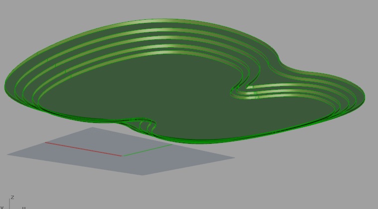
4. Roof Frame

I drew these curves in Rhino at zero level. Number and height of the curves could be changed parametrically through "Number Slider"s. I used four curve parameters for the exterior curves, interior curves, closed curves and smaller closed curves.


I elevated each curve to its own level by using "Unit Z" and "Move" nodes.

I used "Extrude" and "Boundary" nodes. I did not prefer to use "Cap Holes" node here, because I wanted a hole (opening) in the middle.
Final Parametric Model (baked)


Physically Based Part of the Modeling:
After finishing parametric model, I baked the surfaces. There are six curved Etfe Pillows on the roof. On sunny days, Etfe pillows deflate, on cloudy days they are inflated to let more sun light in.


I made use of Weaverbird and Kangaroo engine to inflate the Etfe pillows.

Unary force amplitude could be changed parametrically through "Number Slider".

For the use of Kangaroo engine, mesh is required. I created meshes inside of the curves by recreating the curves through "Control Points" and "Nurbs Curve". For the use of "Springs Line", mesh edges are required. "Weaverbird Split Polygons" node defined the mesh edges on the curved mesh. By using "Naked Points" node, I separated the points to be anchor points and the rest to be forced by "Unary Force". By using Kangaroo engine, I inflated the Etfe Pillows both upwards and downwards (with negative value in the number slider of Unary Force amplitude).


Inflated Etfe Pillows were baked and seen above. Inflated pillows in the opposite direction are below.

Analyses:
I analyzed the skin surface by using Rhino "Curvature Analysis". Concave parts which are shown in blue make it difficult to manufacture if the body was made out of some solid material such as concrete. Therefore, using tensile structure here was a very clever solution.

Zebra Analysis:
The skin requires more smoothness. Horizontal curves which supply basis for the loft should be modified through number sliders. The convex belt of the loft requires smoothness.


Draft Angle Analysis:

Project Movie:
References:
https://en.wikiarquitectura.com/index.php/Villa_Nurbs
http://www.ruiz-geli.com/projects/inprogress/villa-nurbs
https://vimeo.com/86344328
https://www.youtube.com/watch?v=i5Yh0GqFpA4
https://www.youtube.com/watch?v=urTqxtrzA_k
https://www.youtube.com/watch?v=rHYM_bF3nQo&list=PLov22Ah1hX_wL_U-RXBETlknIwrInLdiw&index=2
http://www.grasshopper3d.com/